Basic Shapes in KGeoBag
This section is a description of the basic spaces and surfaces which can be constructed using KGeoBag. All of the
following shapes can be displayed by the executables MeshViewer and GeometryViewer (see visualization-label).
These executables are built and installed along with KGeoBag when it is linked against VTK.
Geometry visualization
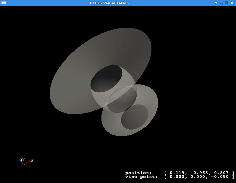
In order to view a geometry you can execute GeometryViewer from the directory $KASPERSYS/install/bin with the
path to your geometry file (.xml) and the name of the geometry element you want to display as the arguments:
./GeometryViewer ../config/TheBag/Examples/ExampleShapes.xml example_rotated_surface
An example of the geometry view is shown below:
To visualized the mesh of a geometric element execute MeshViewer in $KASPERSYS/install/bin with the path to your
geometry file (.xml) and the name of the geometry element you want to display:
./MeshViewer <../config/TheBag/Examples/ExampleShapes.xml> <example_rotated_surface>
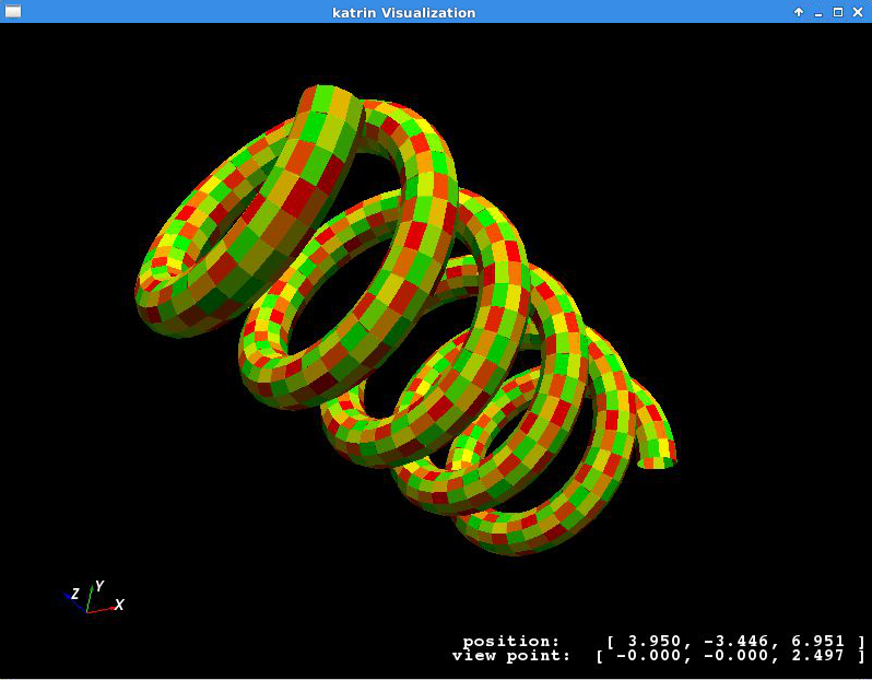
There is also an AxialMeshViewer available, which displays the axial mesh (if defined) in the same way. The
geometric element can be a specific element or several elements collected into a group. To display a single element use
its name, to show a tagged group the argument is written as @tag_group. An example of the mesh viewer being used on
a rod surface is shown below:
The GeometryViewer and MeshViewer will also produce a VTK poly-data file (.vtp) which can then be open in the
external application Paraview for more advanced visualization.
The parameters specifying the method by which a geometric element is meshed must be given in the geometry file when the shape is described. If no mesh is desired for some object, the mesh parameters may be ignored and the defaults will be used. The commands above may also be tried with one of the Kassiopeia simulation examples.
The mesh parameters vary for each object, but essentially describe two properties (for each meshable dimension). These
are the mesh_count and the mesh_power. If the mesh_power is set equal to 1.0, then the mesh_count simply
specifies the number of equally sized segments that a shape will be chopped into, along a particular dimension. If the
mesh_power is greater than 1.0, then the density of segments will increase towards the edges of the shape while
keeping the number of elements the same. The mesh_power property is useful for tailoring the accuracy of mesh
descriptions for Laplace boundary value problems, where quantities such as charge density may vary considerably near the
sharp edges of an object. Therefore, this parameter is mainly used for electrode meshes.
The following sections provide examples and brief descriptions of some basic shapes available for use in KGeoBag.
Basic elements
The following elements (poly-loop and poly-line) are internal descriptors. They can’t be used by themselves outside a geometry element. This section serves as a brief explanation for the structure of these shapes.
Poly-loop
A poly-loop is a closed sequence consisting of several lines and/or arcs that form a polygonal shape. The aequence
starts with <start_point ...> and ends with <last_line ...> or <last_arc ...>, and multiple <next_line
...> or <next_arc ...> elements can be put in between. An example of a poly-loop element is as follows:
<poly_loop>
    <start_point x="0." y="0."/>
    <next_line x="0.4" y="-0.1" line_mesh_count="10" line_mesh_power="2.5"/>
    <next_arc x="-0.1" y="0.4" radius="0.6" right="true" short="false" arc_mesh_count="256"/>
    <last_line line_mesh_count="10" line_mesh_power="2.5"/>
</poly_loop>
which creates a line from (0,0) to (0.4,-0.1) followed by an arc to (-0.1,0.4), and then the loop is closed by a line
back to the starting point. Note that poly-loop and poly-line are two-dimensional objects that operate in (x,y)
coordinates. Any line that is created by a <next_...> command goes from the end-point of the previous line to the
specified coordinate. The directive <last_line ...> or <last_arc ...> connects the first and last points with
the specified segment type.
The arc elements are described with the boolean parameters right and short, as shown here:
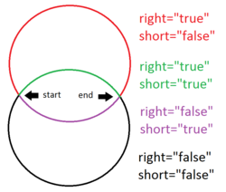
where right="true" means that the circle segment will be drawn clockwise, and vice versa. short="true" means
that the arc will be the shorter one of the two possiblities.
Poly-line
This element is desribed using the same procedure as in poly-loop. However, the first and last points are not necessarily connected. An XML example is below:
<poly_line>
    <start_point x="0.2" y="0.3"/>
    <next_line x="0.1" y="0.1" line_mesh_count="36" line_mesh_power="4.5"/>
    <next_arc x="-0.1" y="0.1" radius="0.2" right="true" short="true" arc_mesh_count="96"/>
    <next_line x="-0.2" y="0.2" line_mesh_count="36" line_mesh_power="1."/>
    <next_line x="-0.3" y="0.1" line_mesh_count="24" line_mesh_power="4.5"/>
</poly_line>
In this case, the sequence progresses through five (x,y) points but does not connect back to the starting point. Hence,
it does not form a closed loop like the poly-loop element does, and does not need a <last_...> command. Otherwise,
the parameters for poly-line are the same as for poly-loop.
Surfaces
Flat surfaces
Flattened circle surface
A flattened circle surface is just a surface with circular shape, where (x,y,z) are the coordinates for the center of the circle and r is the radius:
Works with MeshViewer: Yes.
Works with GeometryViewer: Yes.
An XML example is as follows:
<flattened_circle_surface name="flattened_circle_surface" z="0." flattened_mesh_count="10" flattened_mesh_power="4.">
    <circle x="0.1" y="0.2" radius="0.5" circle_mesh_count="128"/>
</flattened_circle_surface>
Flattened poly-loop surface
A flattened poly loop surface is a surface consisting of several lines, arcs or both, creating a polygon of your desired shape. The first line and the last line are connected automatically. By using the features of the poly-loop outlined above, this provides a very flexible method of designing surface elements.
Works with MeshViewer: Yes.
Works with GeometryViewer: Yes.
An XML example is as follows:
<flattened_poly_loop_surface name="flattened_poly_loop_surface" z="0.1" flattened_mesh_count="10" flattened_mesh_power="4.">
    <poly_loop>
        <start_point x="0." y="0."/>
        <next_line x="0.4" y="-0.1" line_mesh_count="10" line_mesh_power="2.5"/>
        <next_arc x="-0.1" y="0.4" radius="0.6" right="true" short="false" arc_mesh_count="256"/>
        <last_line line_mesh_count="10" line_mesh_power="2.5"/>
    </poly_loop>
</flattened_poly_loop_surface>
Rotated Surfaces
All rotated surfaces are constructed from lines, arcs, poly-lines, or poly-loops which are then rotated around the local x-axis.
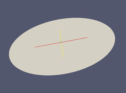
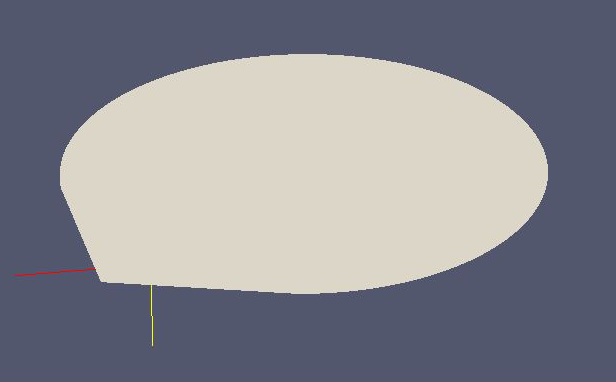
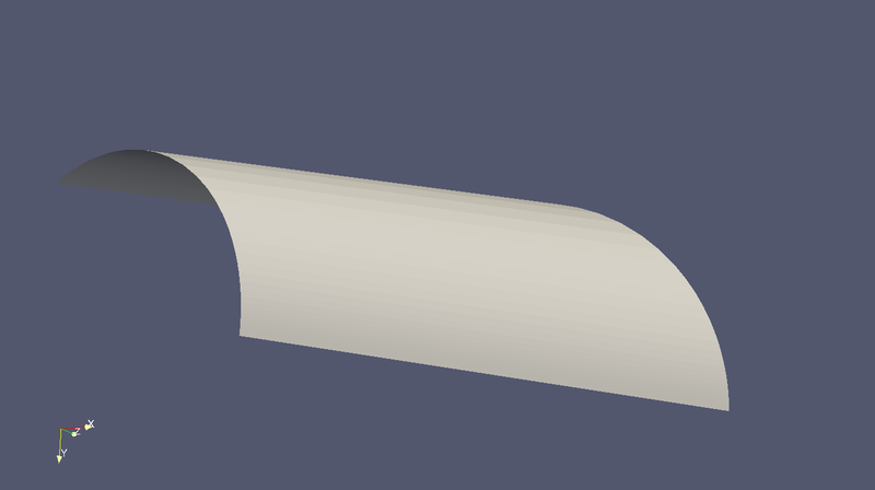
Rotated line segment surface
This type generates the surface of revolution formed by a line that is rotated around the x-axis.
Works with MeshViewer: Yes.
Works with GeometryViewer: Yes.
An XML example is as follows:
<rotated_line_segment_surface name="rotated_line_segment_forward_surface" rotated_mesh_count="96">
    <line_segment x1="0.15" y1="0.1" x2="-0.1" y2="0.05" line_mesh_count="36" line_mesh_power="2.2"/>
</rotated_line_segment_surface>
Rotated arc segment surface
This type generates the surface of revolution formed by an arc that is rotated around the x-axis.
Works with MeshViewer: Yes.
Works with GeometryViewer: Yes.
An XML example is as follows:
<rotated_arc_segment_surface name="rotated_arc_segment_right_short_surface" rotated_mesh_count="128">
    <arc_segment x1="0.15" y1="0.1" x2="-0.1" y2="0.05" radius="0.3" right="true" short="true" arc_mesh_count="64"/>
</rotated_arc_segment_surface>
Rotated poly-line surface
This type generates the surface of revolution created by rotating a poly-line around the local x-axis.
Works with MeshViewer: Yes.
Works with GeometryViewer: Yes.
An XML example is as follows:
<rotated_poly_line_surface name="rotated_poly_line_forward_surface" rotated_mesh_count="64">
    <poly_line>
        <start_point x="0.2" y="0.3"/>
        <next_line x="0.1" y="0.1" line_mesh_count="36" line_mesh_power="4.5"/>
        <next_arc x="-0.1" y="0.1" radius="0.2" right="true" short="true" arc_mesh_count="96"/>
        <next_line x="-0.2" y="0.2" line_mesh_count="36" line_mesh_power="1."/>
        <next_line x="-0.3" y="0.1" line_mesh_count="24" line_mesh_power="4.5"/>
    </poly_line>
</rotated_poly_line_surface>
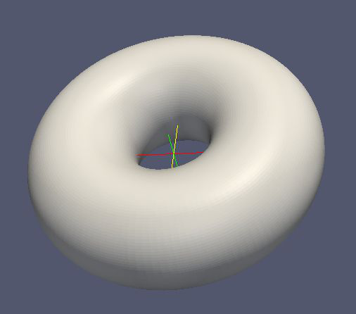
Rotated circle surface
This type generates the surface of revolution created by rotating a circle around the local x-axis. This shape is essentially or torus, or a section of a torus.
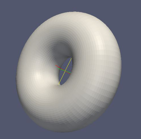
Works with MeshViewer: Yes.
Works with GeometryViewer: Yes.
An XML example is as follows:
<rotated_circle_surface name="rotated_circle_surface" rotated_mesh_count="32">
    <circle x="0.1" y="0.5" radius="0.3" circle_mesh_count="32"/>
</rotated_circle_surface>
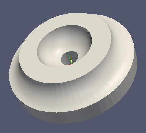
Rotated poly loop surface
This type generates the surface of revolution created by rotating a poly-loop around the local x-axis.
Works with MeshViewer: Yes.
Works with GeometryViewer: Yes.
An XML example is as follows:
<rotated_poly_loop_surface name="rotated_poly_loop_surface" rotated_mesh_count="64">
    <poly_loop>
        <start_point x="0.3" y="0.3"/>
        <next_line x="0.3" y="0.5" line_mesh_count="36" line_mesh_power="2.5"/>
        <next_arc x="0.1" y="0.7" radius="0.25" right="false" short="true" arc_mesh_count="64"/>
        <next_line x="-0.1" y="0.7" line_mesh_count="36" line_mesh_power="2.5"/>
        <next_arc x="-0.3" y="0.5" radius="0.25" right="false" short="true" arc_mesh_count="64"/>
        <next_line x="-0.3" y="0.3" line_mesh_count="36" line_mesh_power="2.5"/>
        <next_arc x="-0.1" y="0.1" radius="0.25" right="false" short="true" arc_mesh_count="64"/>
        <next_line x="0.1" y="0.1" line_mesh_count="36" line_mesh_power="2.5"/>
        <last_arc radius="0.25" right="false" short="true" arc_mesh_count="64"/>
    </poly_loop>
</rotated_poly_loop_surface>
Shell Surfaces
All shell surfaces are lines, arcs or surfaces that are rotated around the x-axis between a given start angle (angle_start) and stop angle (angle_stop).
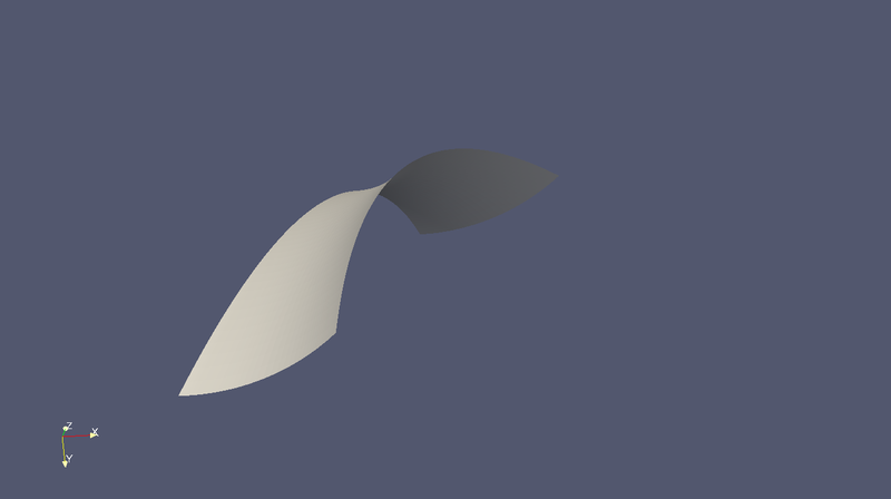
Shell line segment surface
This produces an angularly limited portion of a surface of revolution from a line that is rotated around the local x-axis.
Works with MeshViewer: Yes.
Works with GeometryViewer: Yes.
An XML example is as follows:
<shell_line_segment_surface name="shell_line_segment_forward_surface" angle_start="240" shell_mesh_count="96" shell_mesh_power="6">
    <line_segment x1="0.15" y1="0.1" x2="-0.1" y2="0.05" line_mesh_count="36" line_mesh_power="2.2"/>
</shell_line_segment_surface>
Shell arc segment surface
This produces an angularly limited portion of a surface of revolution from an arc that is rotated around the local x-axis.
Works with MeshViewer: Yes.
Works with GeometryViewer: Yes.
An XML example is as follows:
<shell_arc_segment_surface name="shell_arc_segment_right_short_surface" shell_mesh_count="128" shell_mesh_power="6">
    <arc_segment x1="0.15" y1="0.1" x2="-0.1" y2="0.05" radius="0.3" right="true" short="true" arc_mesh_count="64"/>
</shell_arc_segment_surface>
Shell poly-line surface
This produces an angularly limited portion of a surface of revolution from a poly-line that is rotated around the local x-axis.
Works with MeshViewer: Yes.
Works with GeometryViewer: Yes.
An XML example is as follows:
<shell_poly_line_surface name="shell_poly_line_forward_surface" angle_start="270" angle_stop="120" shell_mesh_count="64" shell_mesh_power="6">
    <poly_line>
        <start_point x="0.2" y="0.3"/>
        <next_line x="0.1" y="0.1" line_mesh_count="36" line_mesh_power="4.5"/>
        <next_arc x="-0.1" y="0.1" radius="0.2" right="true" short="true" arc_mesh_count="96"/>
        <next_line x="-0.2" y="0.2" line_mesh_count="36" line_mesh_power="1."/>
        <next_line x="-0.3" y="0.1" line_mesh_count="24" line_mesh_power="4.5"/>
    </poly_line>
</shell_poly_line_surface>
Shell circle surface
This produces an angularly limited portion of a surface of revolution from a circle that is rotated around the local x-axis.
Works with MeshViewer: Yes.
Works with GeometryViewer: Yes.
An XML example is as follows:
<shell_circle_surface name="shell_circle_surface" angle_start="200" angle_stop="130" shell_mesh_count="32" shell_mesh_power="6">
     <circle x="0.1" y="0.5" radius="0.3" circle_mesh_count="32"/>
 </shell_circle_surface>
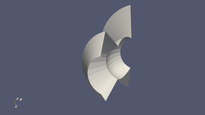
Shell poly-loop surface
This produces an angularly limited portion of a surface of revolution from a poly-loop that is rotated around the local x-axis.
Works with MeshViewer: Yes.
Works with GeometryViewer: Yes.
An XML example is as follows:
<shell_poly_loop_surface name="shell_poly_loop_surface"  angle_start="30" angle_stop="360" shell_mesh_count="64" shell_mesh_power="6">
    <poly_loop>
        <start_point x="0.3" y="0.3"/>
        <next_line x="0.3" y="0.5" line_mesh_count="64" line_mesh_power="2.5"/>
        <next_arc x="0.1" y="0.7" radius="0.25" right="false" short="true" arc_mesh_count="64"/>
        <next_line x="-0.1" y="0.7" line_mesh_count="64" line_mesh_power="2.5"/>
        <next_arc x="-0.3" y="0.5" radius="0.25" right="false" short="true" arc_mesh_count="64"/>
        <next_line x="-0.3" y="0.3" line_mesh_count="64" line_mesh_power="2.5"/>
        <next_arc x="-0.1" y="0.1" radius="0.25" right="false" short="true" arc_mesh_count="64"/>
        <next_line x="0.1" y="0.1" line_mesh_count="64" line_mesh_power="2.5"/>
        <last_arc radius="0.25" right="false" short="true" arc_mesh_count="64"/>
    </poly_loop>
</shell_poly_loop_surface>
Extruded Surfaces
Extruded surfaces are surfaces that are extruded along the direction of the local z-axis from a minimum z-position (zmin) to a maximum z-position (zmax).
Extruded poly-line surface
This generates a surface by extruding a poly-line.
An XML example is as follows:
<extruded_poly_line_surface name="extruded_poly_line_surface" zmin="-0.3" zmax="0.2" extruded_mesh_count="96" extruded_mesh_power="6.3">
    <poly_line>
        <start_point x="-0.3" y="0.1"/>
        <next_line x="-0.2" y="0.2" line_mesh_count="24" line_mesh_power="4.5"/>
        <next_line x="-0.1" y="0.1" line_mesh_count="36" line_mesh_power="1."/>
        <next_arc x="0.1" y="0.1" radius="0.2" right="false" short="true" arc_mesh_count="96"/>
        <next_line x="0.2" y="0.3" line_mesh_count="36" line_mesh_power="4.5"/>
    </poly_line>
</extruded_poly_line_surface>
Extruded circle surface
This generates the surfaced produced by extruding a circle (this is the same as a cylinder).
Works with MeshViewer: Yes.
Works with GeometryViewer: Yes.
An XML example is as follows:
<extruded_circle_surface name="extruded_circle_surface" zmin="-0.1" zmax="0.1" extruded_mesh_count="32" extruded_mesh_power="1">
    <circle x="0.1" y="0.5" radius="0.3" circle_mesh_count="128"/>
</extruded_circle_surface>
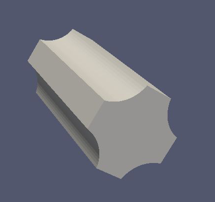
Extruded poly-loop surface
This generates a surface by extruding a poly-loop.
Works with MeshViewer: Yes.
Works with GeometryViewer: Yes.
An XML example is as follows:
<extruded_poly_loop_surface name="extruded_poly_loop_surface" zmin="-0.3" zmax="0.3" extruded_mesh_count="37" extruded_mesh_power="6.3">
    <poly_loop>
        <start_point x="0.3" y="0.3"/>
        <next_line x="0.3" y="0.5" line_mesh_count="36" line_mesh_power="2.5"/>
        <next_arc x="0.1" y="0.7" radius="0.25" right="false" short="true" arc_mesh_count="64"/>
        <next_line x="-0.1" y="0.7" line_mesh_count="36" line_mesh_power="2.5"/>
        <next_arc x="-0.3" y="0.5" radius="0.25" right="false" short="true" arc_mesh_count="64"/>
        <next_line x="-0.3" y="0.3" line_mesh_count="36" line_mesh_power="2.5"/>
        <next_arc x="-0.1" y="0.1" radius="0.25" right="false" short="true" arc_mesh_count="64"/>
        <next_line x="0.1" y="0.1" line_mesh_count="36" line_mesh_power="2.5"/>
        <last_arc radius="0.25" right="false" short="true" arc_mesh_count="64"/>
    </poly_loop>
</extruded_poly_loop_surface>
Special Surfaces
These surfaces are just specific cases of the more general surface types already listed. However, since their use is extremely common, they have been made available as unique, special types. For many simple simulations, it is possible to design the geometry entirely using these elements.
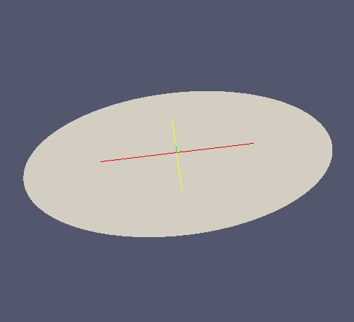
Disk surface
This produces a disk centered on the local z-axis.
Works with MeshViewer: Yes.
Works with GeometryViewer: Yes.
An XML example is as follows:
<disk_surface name="disk_surface" z=".01" r=".35" radial_mesh_count="14" radial_mesh_power="5" axial_mesh_count="20"/>
The parameters are:
z: z-position in meters
r: radius in meters
radial_mesh_count: radial mesh parameter (default is 1)
radial_mesh_power: radial meshing power (default is 1.)
axial_mesh_count: axial mesh parameter (default is 16)
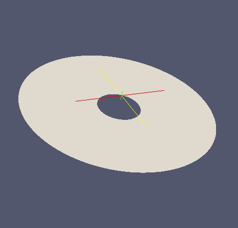
Annulus surface
This produces an annulus centered on the z axis.
Works with MeshViewer: Yes.
Works with GeometryViewer: Yes.
An XML example is as follows:
<annulus_surface name="annulus_surface" z="-.01" r1="0.1" r2="0.45" radial_mesh_count="22" radial_mesh_power="1.5" axial_mesh_count="32"/>
The parameters are:
z: z-position in meters
r1: the first of the radii in meters
r2: the second radius in meters
radial_mesh_count: radial mesh parameter (default is 1)
radial_mesh_power: radial meshing power (default is 1.)
axial_mesh_count: axial mesh parameter (default is 16)
Cylinder surface
Generates a cylinder centered on the z axis.
Works with MeshViewer: Yes.
Works with GeometryViewer: Yes.
An XML example is as follows:
<cylinder_surface name="cylinder_surface" z1="-0.3" z2="0.4" r="0.55" longitudinal_mesh_count="15" longitudinal_mesh_power="2." axial_mesh_count="32"/>
The parameters are:
z1: the first z position in meters
z2: the second z position in meters
r: radius in meters
longitudinal_mesh_count: longitudinal mesh parameter (default is 1)
longitudinal_mesh_power: longitudinal meshing power (default is 1.)
axial_mesh_count: axial mesh parameter (default is 16)
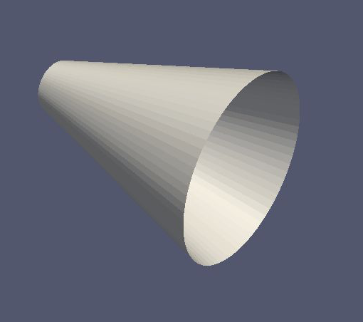
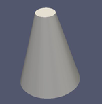
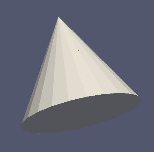
Cone Surface
Generates a cone centered on the z axis.
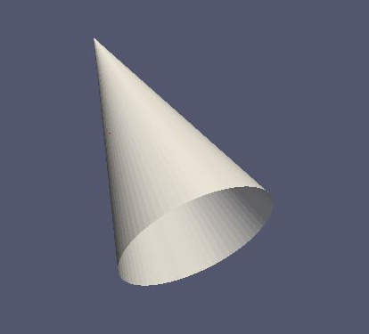
Works with MeshViewer: Yes.
Works with GeometryViewer: Yes.
An XML example is as follows:
<cone_surface name="cone_surface" za="-0.4" zb="0.4" rb="0.25" longitudinal_mesh_count="48" longitudinal_mesh_power="1." axial_mesh_count="72"/>
The parameters are:
za: apex z position in meters
zb: base z position in meters
rb: base radius in meters
longitudinal_mesh_count: longitudinal mesh parameter (default is 1)
longitudinal_mesh_power: longitudinal meshing power (default is 1.)
axial_mesh_count: axial mesh parameter (default is 16)
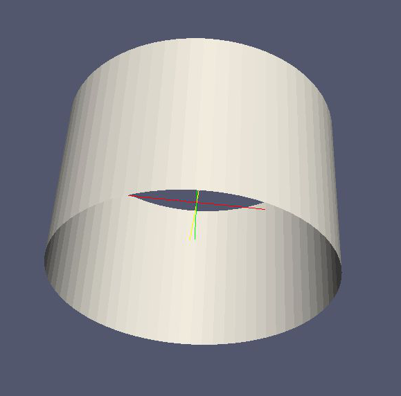
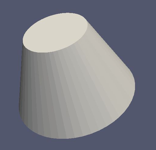
Cut Cone Surface
Produces a truncated cone centered on the local z-axis.
Works with MeshViewer: Yes.
Works with GeometryViewer: Yes.
An XML example is as follows:
<cut_cone_surface name="cut_cone_surface" z1="0.5" r1="0.6" z2="-0.1" r2="0.2" longitudinal_mesh_count="23" longitudinal_mesh_power="4." axial_mesh_count="48"/>
The parameters are:
z1: the first z coordinates in meters
r1: the first r coordinates in meters
z2: the second z coordinate in meters
r2: the second r coordinate in meters
longitudinal_mesh_count: longitudinal mesh parameter (default is 1)
longitudinal_mesh_power: longitudinal meshing power (default is 1.)
axial_mesh_count: axial mesh parameter (default is 16)
Torus Surface
Generates a torus centered on the local z axis.
Works with MeshViewer: Yes.
Works with GeometryViewer: Yes.
An XML example is as follows:
<cut_torus_surface name="cut_torus_surface" z1="0.3" r1="0.1" z2="-0.1" r2="0.2" radius="0.3" right="true" short="true" toroidal_mesh_count="128" axial_mesh_count="256"/>
The parameters are:
z: z coordinate of the center in meters
r: r coordinate of the center in meters
radius: the toroidal radius in meters
toroidal_mesh_count: toroidal mesh parameter (default is 64)
axial_mesh_count: axial mesh parameter (default is 64)
Cut Torus Surface
Produces an angularly limited toroidal section centered on the z axis.
Works with MeshViewer: Yes.
Works with GeometryViewer: Yes.
An XML example is as follows:
<torus_surface name="torus_surface" z="0.2" r="0.5" radius="0.35" toroidal_mesh_count="256" axial_mesh_count="512"/>
The parameters are:
z1: the first z coordinate in meters
r1: the first r coordinate in meters
z2: the second z coordinate in meters
r2: the second r coordinate in meters
radius: the toroidal radius in meters
right: is the arc on the right side of the directed line connecting point 1 to point 2?
short: does the arc subtend less than pi radians?
toroidal_mesh_count: toroidal mesh parameter (default is 64)
axial_mesh_count: axial mesh parameter (default is 64)
Spaces
Spaces are considered distinct from surfaces as they are (water-tight) volumes. The cannot be open or have holes which puncture their boundaries. In the Kassiopeia interface, spaces are treated very differently than surfaces and have different features on purposes.
Extruded Spaces
Extruded spaces are from in a manner similar to extruded surfaces, the only difference being that they also provide planar caps to fully enclose a central volume.
Extruded Circle Space
Generates a volume by extruding a cycle (cynlinder).
Works with MeshViewer: Yes.
Works with GeometryViewer: Yes.
An XML example is as follows:
<extruded_circle_space name="extruded_circle_space" zmin="-0.1" zmax="0.1" extruded_mesh_count="32" extruded_mesh_power="1" flattened_mesh_count="28" flattened_mesh_power="1.4">
    <circle x="0.1" y="0.5" radius="0.3" circle_mesh_count="128"/>
</extruded_circle_space>
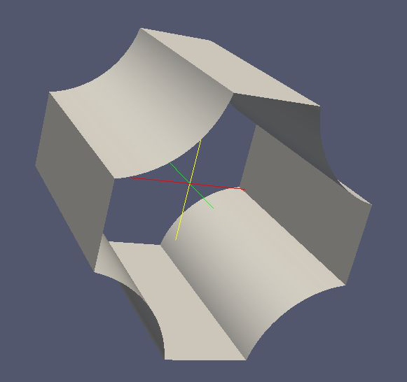
Extruded Poly-Loop Space
Generates a volume by extruding a poly-loop.
Works with MeshViewer: Yes.
Works with GeometryViewer: Yes.
An XML example is as follows:
<extruded_poly_loop_space name="extruded_poly_loop_space" zmin="-0.7" zmax="0.7" extruded_mesh_count="37" extruded_mesh_power="6.3" flattened_mesh_count="28" flattened_mesh_power="1.4">
    <poly_loop>
        <start_point x="0.3" y="0.3"/>
        <next_line x="0.3" y="0.5" line_mesh_count="36" line_mesh_power="2.5"/>
        <next_arc x="0.1" y="0.7" radius="0.25" right="false" short="true" arc_mesh_count="64"/>
        <next_line x="-0.1" y="0.7" line_mesh_count="36" line_mesh_power="2.5"/>
        <next_arc x="-0.3" y="0.5" radius="0.25" right="false" short="true" arc_mesh_count="64"/>
        <next_line x="-0.3" y="0.3" line_mesh_count="36" line_mesh_power="2.5"/>
        <next_arc x="-0.1" y="0.1" radius="0.25" right="false" short="true" arc_mesh_count="64"/>
        <next_line x="0.1" y="0.1" line_mesh_count="36" line_mesh_power="2.5"/>
        <last_arc radius="0.25" right="false" short="true" arc_mesh_count="64"/>
    </poly_loop>
</extruded_poly_loop_space>
Rotated Spaces
Rotated Line Segment
Generates a volume enclosed by a surface of revolution produced from rotating a line segement.
Works with GeometryViewer: Yes.
Works with MeshViewer: Yes.
An XML example is as follows:
<rotated_line_segment_space name="rotated_line_segment_space" rotated_mesh_count="100" flattened_mesh_count="10" flattened_mesh_power="2.2">
    <line_segment x1="0.15" y1="0.1" x2="-0.1" y2="0.05" line_mesh_count="10" line_mesh_power="2.2"/>
</rotated_line_segment_space>
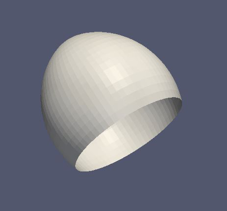
Rotated Arc Segment
Generates a volume enclosed by a surface of revolution produced from rotating an arc segment.
Works with GeometryViewer: Yes.
Works with MeshViewer: Yes.
An XML example is as follows:
<rotated_arc_segment_space name="rotated_arc_segment_space" rotated_mesh_count="128" flattened_mesh_count="10" flattened_mesh_power="1.5">
    <arc_segment x1="0.15" y1="0.1" x2="-0.1" y2="0.03" radius="0.5" right="true" short="true" arc_mesh_count="64"/>
</rotated_arc_segment_space>
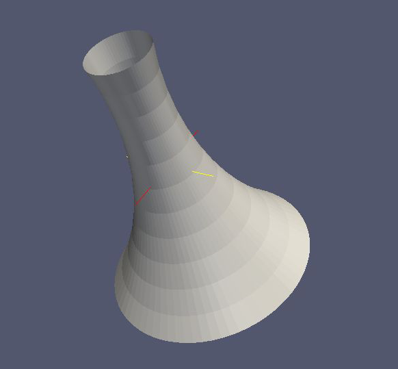
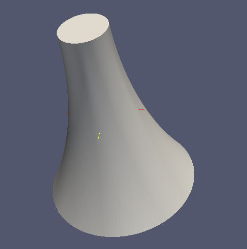
Rotated Poly-Line Space
Generates a volume enclosed by a surface of revolution produced from rotating a poly-line.
Works with GeometryViewer: Yes.
Works with MeshViewer: Yes.
An XML example is as follows:
<rotated_poly_line_space name="rotated_poly_line_reverse_space" rotated_mesh_count="128" flattened_mesh_count="36" flattened_mesh_power="3.8">
    <poly_line>
        <start_point x="-0.1" y="0.1"/>
        <next_arc x="-0.3" y="0.3" radius="0.315" right="false" short="true" arc_mesh_count="24"/>
        <next_line x="0.2" y="0.4" line_mesh_count="52" line_mesh_power="3.5"/>
        <next_line x="0.1" y="0.1" line_mesh_count="24" line_mesh_power="2."/>
    </poly_line>
</rotated_poly_line_space>
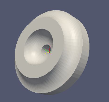
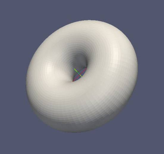
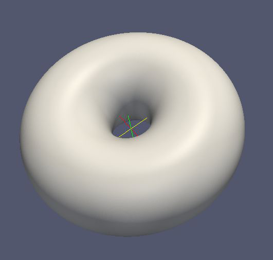
Rotated Circle Space
Generates a volume by rotating a circle (torus).
Works with GeometryViewer: Yes.
Works with MeshViewer: Yes.
An XML example is as follows:
<rotated_circle_space name="rotated_circle_space" rotated_mesh_count="128">
    <circle x="0.1" y="0.5" radius="0.3" circle_mesh_count="128"/>
</rotated_circle_space>
Rotated Poly-Loop Space
Generates a volume enclosed by a surface of revolution produced from rotating a poly-loop
Works with GeometryViewer: No.
Works with MeshViewer: Yes.
An XML example is as follows:
<rotated_poly_loop_space name="rotated_poly_loop_space" rotated_mesh_count="64">
    <poly_loop>
        <start_point x="0.3" y="0.3"/>
        <next_line x="0.3" y="0.5" line_mesh_count="36" line_mesh_power="2.5"/>
        <next_arc x="0.1" y="0.7" radius="0.25" right="false" short="true" arc_mesh_count="64"/>
        <next_line x="-0.1" y="0.7" line_mesh_count="36" line_mesh_power="2.5"/>
        <next_arc x="-0.3" y="0.5" radius="0.25" right="false" short="true" arc_mesh_count="64"/>
        <next_line x="-0.3" y="0.3" line_mesh_count="36" line_mesh_power="2.5"/>
        <next_arc x="-0.1" y="0.1" radius="0.25" right="false" short="true" arc_mesh_count="64"/>
        <next_line x="0.1" y="0.1" line_mesh_count="36" line_mesh_power="2.5"/>
        <last_arc radius="0.25" right="false" short="true" arc_mesh_count="64"/>
    </poly_loop>
</rotated_poly_loop_space>
Special Spaces
These spaces are just specific cases of the more general space types already listed. They have been made separately available because of their common use. As with the special surfaces, these elements may be used to design a simple simulation geometry.
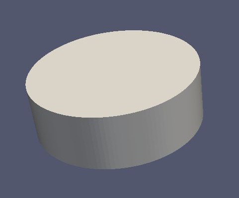
Cylinder Space
Produces a cylinder space centered on the local z axis.

Works with MeshViewer: Yes.
Works with GeometryViewer: Yes.
An XML example is as follows:
<cylinder_space name="cylinder_space" z1="-0.4" z2="0.4" r="0.3" longitudinal_mesh_count="32" longitudinal_mesh_power="2." radial_mesh_count="24" radial_mesh_power="1.5" axial_mesh_count="32"/>
- The parameters are:
z1: the first z coordinate in meters
z2: the second z coordinate in meters
r: the radius in meters
longitudinal_mesh_count: longitudinal mesh parameter (default is 1)
longitudinal_mesh_power: longitudinal meshing power (default is 1.)
radial_mesh_count: radial mesh parameter (default is 1)
radial_mesh_power: radial meshing power (default is 1.)
axial_mesh_count: axial mesh parameter (default is 16)
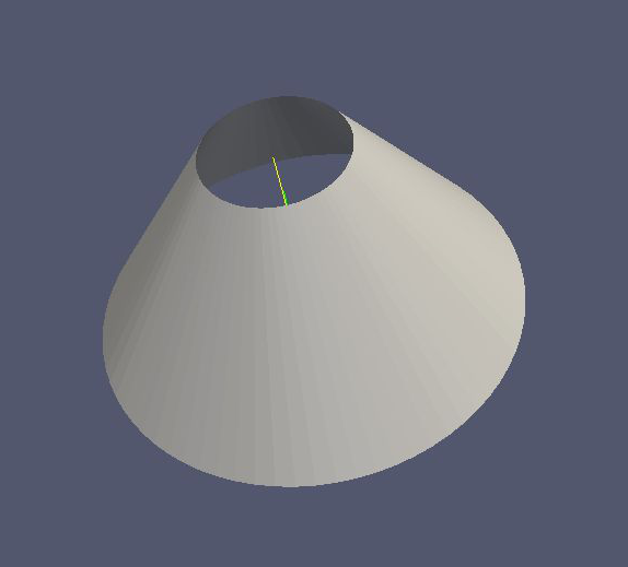
Cone Space
Generates a conical space centered on the local z axis.
Works with MeshViewer: Yes.
Works with GeometryViewer: Yes.
An XML example is as follows:
<cone_space name="cone_space" za="-0.1" zb="0.65" rb="0.4" longitudinal_mesh_count="28" longitudinal_mesh_power="1.8" radial_mesh_count="56" radial_mesh_power="1." axial_mesh_count="24"/>
The parameters are:
za: apex z position in meters
zb: base z position in meters
rb: base radius in meters
longitudinal_mesh_count: longitudinal mesh parameter (default is 1)
longitudinal_mesh_power: longitudinal meshing power (default is 1.)
radial_mesh_count: radial mesh parameter (default is 1)
radial_mesh_power: radial meshing power (default is 1.)
axial_mesh_count: axial mesh parameter (default is 16)
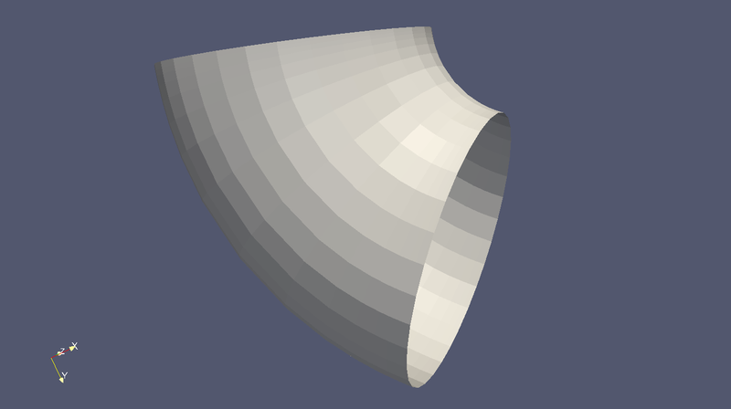
Cut Cone Space
Produces a cut cone volume (frustrum).
Works with MeshViewer: Yes.
Works with GeometryViewer: Yes.
An XML example is as follows:
<cut_cone_space name="cut_cone_space" z1="-0.3" r1="0.4" z2="0.2" r2="0.2" longitudinal_mesh_count="88" longitudinal_mesh_power="1." radial_mesh_count="28" radial_mesh_power="1.6" axial_mesh_count="50"/>
The parameters are:
z1: the first z coordinate in meters
r1: the first r coordinate in meters
z2: the second z coordinate in meters
r2: the second r coordinate in meters
longitudinal_mesh_count: longitudinal mesh parameter (default is 1)
longitudinal_mesh_power: longitudinal meshing power (default is 1.)
radial_mesh_count: radial mesh parameter (default is 1)
radial_mesh_power: radial meshing power (default is 1.)
axial_mesh_count: axial mesh parameter (default is 16)
Works with MeshViewer: Yes.
Works with GeometryViewer: Yes.
Torus Space
Produces a torus centered on the local z axis.
Works with MeshViewer: Yes.
Works with GeometryViewer: Yes.
An XML example is as follows:
<torus_space name="torus_space" z="0.2" r="0.5" radius="0.35" toroidal_mesh_count="256" axial_mesh_count="512"/>
The parameters are:
z: z coordinate of the center in meters
r: r coordinate of the center in meters
radius: the toroidal radius in meters
toroidal_mesh_count: toroidal mesh parameter (default is 64)
axial_mesh_count: axial mesh parameter (default is 64)
Cylinder Tube Space
Creates a tube, (a hollow cylinder with finite wall thickness).
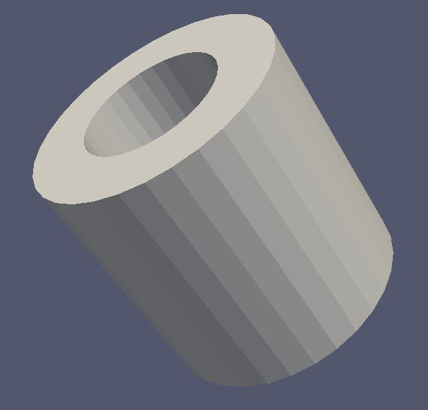
Works with MeshViewer: Yes.
Works with GeometryViewer: Yes.
An XML example is as follows:
<cylinder_tube_space name="cylinder_tube_space" z1="-0.45" r1="0.25" z2="0.45" r2="0.45" longitudinal_mesh_count="32" longitudinal_mesh_power="2." radial_mesh_count="24" radial_mesh_power="1.5" axial_mesh_count="32"/>
The parameters are:
z1: the first z position in meters
z2: the second z position in meters
r1: the first radius in meters
r2: the second radius in meters
longitudinal_mesh_count: longitudinal mesh parameter (default is 1)
longitudinal_mesh_power: longitudinal meshing power (default is 1.)
radial_mesh_count: radial mesh parameter (default is 1)
radial_mesh_power: radial meshing power (default is 1.)
axial_mesh_count: axial mesh parameter (default is 16)
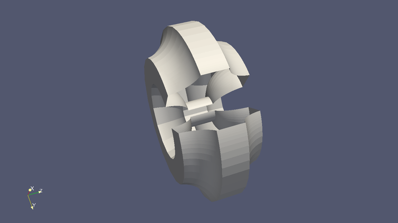
Cut Cone Tube Space
Generates a tubular frustrum (a cut cone with central axially symmetric void).
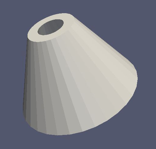
Works with MeshViewer: Yes.
Works with GeometryViewer: Yes.
An XML example is as follows:
<cut_cone_tube_space name="cut_cone_tube_space" z1="-0.3" z2="0.3" r11="0.3" r12="0.48" r21="0.1" r22="0.18" longitudinal_mesh_count="32" longitudinal_mesh_power="2." radial_mesh_count="24" radial_mesh_power="1.5" axial_mesh_count="32"/>
The parameters are:
z1: the first side’s z position in meters
z2: the second side’s z position in meters
r11: one of the side’s first radius in meters
r12: the other side’s first radius in meters
r21: one of the side’s second radius in meters
r22: the other side’ second radius in meters
longitudinal_mesh_count: longitudinal mesh parameter (default is 1)
longitudinal_mesh_power: longitudinal meshing power (default is 1.)
radial_mesh_count: radial mesh parameter (default is 1)
radial_mesh_power: radial meshing power (default is 1.)
axial_mesh_count: axial mesh parameter (default is 16)
Box Space
Produces an axis aligned rectangular prism.
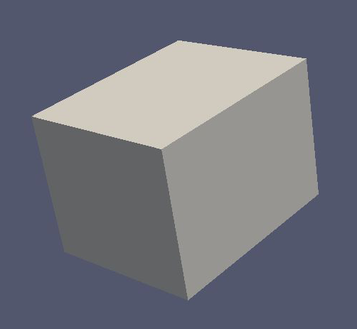
Works with MeshViewer: No.
Works with GeometryViewer: Yes.
An XML example is as follows:
<box_space name="box_space" xa="0.1" xb="0.65" x_mesh_count="1000" x_mesh_power="5.5" ya="-0.4" yb="0.3" y_mesh_count="100" y_mesh_power="1.8" za="0.4" zb="-0.1" z_mesh_count="10" z_mesh_power="1."/>
The parameters are:
xa: one of the x extrema in meters
xb: the other x extremum in meters
x_mesh_count: x mesh count
x_mesh_power: x mesh power
ya: one of the y extrema in meters
yb: the other y extremum in meters
y_mesh_count: y mesh count
y_mesh_power: y mesh power
za: one of the z extrema in meters
zb: the other z extremum in meters
z_mesh_count: z mesh count
z_mesh_power: z mesh power